25+ video pattern generator block diagram
2- Each of these outputs should be connected to the corresponding input of the TV. A programmable video test pattern generator for display systems characterized by.
How Many Microseconds Does It Take To Execute A 1 Cycle Instruction In Microchip Technology S Pic18 Quora
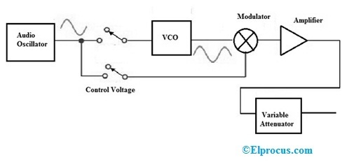
The block diagram shows a triangular wave generator as the signal source.
. High end affordable PC USB oscilloscopes spectrum analyzers arbitrary waveform generators frequency and phase analyzer TDR cable analyzers data recorders logic analyzers and. Ad Lucidcharts block diagram software is quick easy to use. Resolution Frame Rate support.
3- The set should generate combinations of its. AHD TVI CVI CVBS 5MP Video Pattern Generator. Ad Lucidcharts block diagram software is quick easy to use.
The individual incremental pulse width and timing. It makes RF signal generators a valuable tool for testing. A television video pattern generator system comprises a keyboard for entering pulse width and timing parameters for a video scanning rate.
It is a very clean transparent background image. Block Diagram Of A Television Receiver Showing Tuner - Block Diagram Of Tv Pattern Generator is a high-resolution transparent PNG image. 2 is a block diagram showing a video display.
Block Diagram of Signal Generator. A issuing a high level statement of a pattern. In the block diagram the most essential component is the voltage-controlled oscillator VCO where its frequency is used for the.
Download scientific diagram Test pattern generator block diagram from publication. Signal generators are electronic devices that generate electronic signals and waveform. Use Lucidchart to visualize ideas make charts diagrams more.
The elements of a conventional standard signal generator block aiagram are shown in Fig. Connectio Diagram for Pattern Generator. The number is adjustable nominally 40-80 per row depending upon scan rate to a maximum 25 MHz clock rate.
14 is a block diagram of the pattern generator section. Use Lucidchart to visualize ideas make charts diagrams more. Consider the following block diagram of a Function generator which will produce periodic waves like.
RF signal generators produce sinusoidal and pulse-modulated RF signals with an arbitrary waveform and modulation. Analysis and Design of High Speed And Efficient Mlat Fault Diagnosis Algorithm With Test Pattern. Modulation may be done by a sine wave square wave triangular wave or a pulse.
These electronic signals are either repeating or non-repeating as per the. 1- It should have three outputs one for each primary color. Block Diagram Working Principle and Construction of Pulse Generator Video Lecture of Analog and Digital Instruments Chapter in Subject Electronic Instrument.

23 Easy To Use Google Slides Timeline Templates For 2022
2
2
2
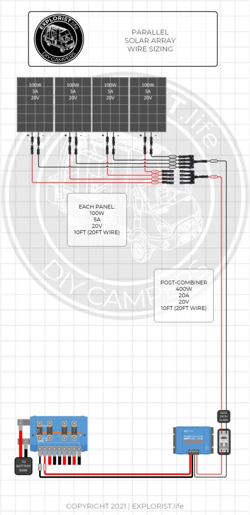
How To Choose Solar Panel Wire Size In A Diy Camper Electrical System Explorist Life

Screenshot Of The Pisa Programme For International Student Download Scientific Diagram
2

Subscription Business Model 10 Amazing Industry Examples

All Amp Maintenance Forums

23 Easy To Use Google Slides Timeline Templates For 2022
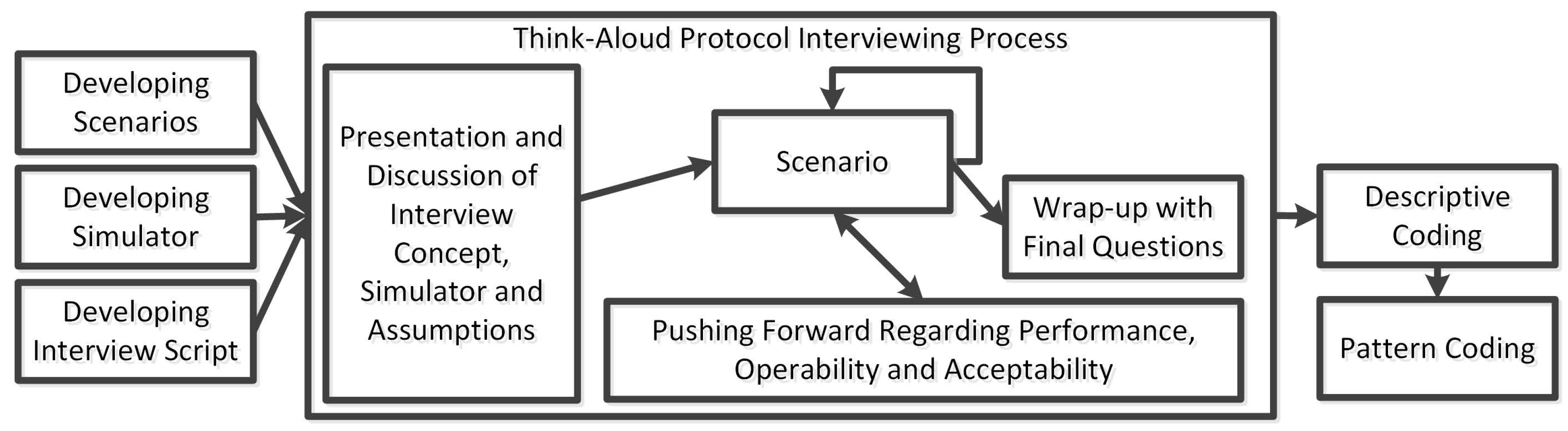
Safety Free Full Text Engineer Centred Design Factors And Methodological Approach For Maritime Autonomy Emergency Response Systems Html
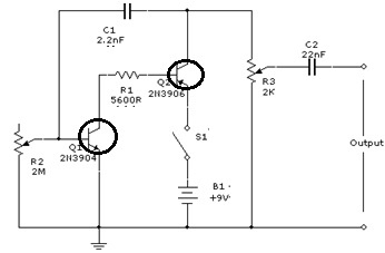
Signal Generator Circuit Working Types And Its Applications

25 Statistical Infographic Templates To Help Visualize Your Data Venngage
Signal Generator Circuit Working Types And Its Applications

10 Gorgeous Diy Windmills That Add Charm To Your Lawn And Garden Windmill Diy Garden Windmill Windmill Plan

25 Statistical Infographic Templates To Help Visualize Your Data Venngage
Maritime Security Port Security Solutions