peripheral interface components wiring diagram
SPECIAL WIRING DIAGRAM FIGURE 3 8 MECHANICAL CABLE CONNECTION FIGURES 4 AND 5 9 SYSTEM START-UP PROCEDURE 10 SYSTEM POWER DOWN INSTRUCTIONS 10. Electronic components are static sensitive.
Circuit Diagram Of The Counter 8254 And Programmable Peripheral Download Scientific Diagram
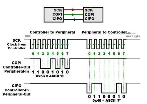
The Serial Peripheral Interface SPI bus was developed by Motorola to provide full-duplex synchronous serial communication between master and slave devices.
. 35 x 100 mm on the D20 IO Peripheral DB25 Field wiring is terminated onto the D20 IO peripheral through DB25 connectors Compression Disconnect Field wiring is terminated onto plug-on terminator blocks 12 AWG 205mm max blade screwdriver - 06 x 35 x 100 mm which then mate with board-mounted headers on the D20 IO Peripheral. The protocol which stands for Serial Peripheral Interface is different to the I2C serial protocol in a. The diagram below demonstrate how to used NFC devices with your microcontrollers.
Figure 2-2 4020 System Block Diagram Intelligent Supply Installation 2-5. It uses separate clock and data lines along with a select line to choose the device you wish to talk to. Trailer Wiring Diagram is a simple yet helpful way to know the proper way of wiring your trailer efficiently and properly.
The frequency-modulated phase-locked loop FMPLL clock module is used to multiply the external. Provides the DC power required for operation of the. Some examples require external components such as switches or sensors.
This protocol can be implemented very easily and quickly with fewer IO pins. RC522 RFID Module Pinout. The SBC 8010 computer system contains 48 programmable IO lines implemented with Intel 8255 Programmable Peripheral Interface components.
Before I go ripping out whats left of factory components to get this right any help on wiring digrams would be helpful. Use proper static precautions static. To system hardware or wiring.
In embedded systems due to constraints of less number of GPIO pins we use serial peripheral interface to transfer data between two devices by using the minimum number of GPIO pins. CircuitPython Digital In Out. Wiring Diagram For Trailer Light 7 Pin Http.
Knockouts are available on 3 sides for routing of peripheral cables. Wiring Diagram for Usb Plug wiring diagram is a simplified tolerable pictorial representation of an electrical circuitIt shows the components of the circuit as simplified shapes and the facility and signal contacts in the middle of the devices. SPI communication saves us wiring pins and also reduces the cost of hardware.
The ECLK frequency is a user-programmable ratio of the peripheral interface clock VCLK frequency. Its difficult to understand why rear speakers are. The system software is used to configure the IO lines in user.
I 2 C requires a mere two wires like asynchronous serial but those two wires can support up to 1008 peripheral devices. Now I am looking for wiring diagrams for other things like the brake reverse odometeric ticker etc. Electronic components are static sensitive.
Holds the controller board PCB power supply relay expansion board optional and battery back-up optional. Australian Trailer Plug and Socket Pinout Wiring 7 pin Flat and Round. Chapter 1 - Introduction System Overview 1 Introduction Thank you for purchasing the finest product of its kind available to the Self Storage industry.
Serial Peripheral Interface SPI is an interface bus commonly used to send data between microcontrollers and small peripherals such as shift registers sensors and SD cards. According to Wiring Diagram 12 Volt To Usb there are only four wires used in the cable. This low frequency output can be monitored externally as an indicator of.
As you can see the diagram below there are two options the first option is wired using i2C 2 Wire Communication second option is wired using SPI Serial Peripheral Interface below are the component required for this test. 22 Components 221 Controller box A RAC 4XT Enclosure Access Door. The Serial Peripheral Interface SPI is a synchronous serial communication interface specification used for short-distance communication primarily in embedded systemsThe interface was developed by Motorola in the mid-1980s and has become a de facto standardTypical applications include Secure Digital cards and liquid crystal displays.
All components circuits system operations or software functions known to be. Also unlike SPI I 2 C can support a multi-controller system allowing more than one controller 1 to communicate with all peripheral 1 devices on the bus although the controller devices cant talk to each other over the bus and must take turns using the bus. Controller communicates with peripheral interface cards and directs system.
Question on interface for gm_geek Peripheral or Metra VT. The SBC8010 parallel IO interface is configured by the OEM using the system software. 14 Functional Block Diagram.
PERIPHERAL INTERFACE INSTALLATION 5 TMS MPC FOR TOKHEIM WIRING DIAGRAM FIGURE 2 6 DANGERS WARNINGS AND CAUTIONS 7 CONNECTION INSTRUCTIONS FOR THE SYSTEM 8. PERIPHERAL INTERFACE INSTALLATION 5 TMS MPC for GILBARCO WIRING DIAGRAM FIGURE 2 6. Use proper static precautions static straps before working on the equipment.
SPI Serial Peripheral Interface is an interface bus commonly used for communication with flash memory sensors real-time clocks RTCs analog-to-digital converters and more. The USB device that uses full speed bandwidth devices must have a twisted pair D. LSI interface components for parallel and serial IO.
Youll find wiring diagrams where applicable to show you how to wire up the necessary components to work with each example.

Example Of The Serial Peripheral Interface Spi Wiring Structure Download Scientific Diagram

Peripheral P35 Car Audio Universal Two Channel Adjustable Line Output Rca Converter New Peripheral P35

Spi Tutorial Jtag Boundary Scan In System Programming Bus Analyzers Corelis
Serial Peripheral Interface Spi Learn Sparkfun Com